The wire color code is a very important thing to note. Especially for electricians, electrical engineers, technicians and even regulars.
Installation standards and guidelines for wiring are designed to protect individuals and property from electrical shock and fire hazards. They are typically based on a model code developed by a national or international standards organization, such as the IEC, (with or without local amendments).
In that case, the “optional” wire colors are dictated by local custom. IEC, AC: Most of Europe adheres to IEC (International Electrotechnical Commission) wiring color codes for AC branch circuits.
This article offer you to understand the designations of electrical wiring, find out the IEC standards and learn how to read the letter codes of the wires in the diagrams. In addition, we will tell you how to check the compliance of the connected core with its purpose using an indicator screwdriver or a multimeter.
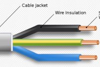
Electric Wire Color Code
Electrical wiring is an electrical equipment and cable installation. Electronic plates, switches, sockets and room illumination may be used.
The cables have to be taken attentively. The safety and installation requirements must be followed. The wire types and their size are strictly categorized according to operating voltage and power. Temperature, exposure, humidity and chemical levels are not only well prepared.
The standard for electric cables and electric cables are manufactured for the purpose of providing the best protection for individuals and equipment.
AC wire color codes IEC
| Function | Label | Color – IEC | Color – Old ICEC |
| Protective earth | Black or red | Green – yellow | Green – yellow |
| Neutral | N | Blue | Blue |
| Line – Single Phase | L | Brown | Brown or Black |
| Line – 3 Phase | L1 | Brown | Brown or Black |
| Line – 3 Phase | L2 | Black | Brown or Black |
| Line – 3 Phase | L3 | Grey | Brown or Black |
AC UK Cable Color code
The UK now uses the Color Codes for cabling IEC AC. This table and the obsolete color codes are listed below. See Cook to connect new colored cables to existing color cables.
| Function | Label | Color – IEC | Color – Old ICEC |
| Protective earth | Black or red | Green – yellow | Green – yellow |
| Neutral | N | Blue | Black |
| Line – Single Phase | L | Brown | Red |
| Line – 3 Phase | L1 | Brown | Red |
| Line – 3 Phase | L2 | Black | Yellow |
| Line – 3 Phase | L3 | Grey | Blue |
United States AC Wire Color Code
The US National Electrical Code only allows the neutral power conductor to be white (or grey) and the protective earth to be bare copper, green, or green with a yellow stripe. Any other colors other than these can, in principle, be used for power conductors. The colors that have been adopted as local practice are shown in the following table.
For 208 three-phase VAC, black, red, and blue are used; for 480 VAC, brown, orange and yellow are used. Conductors larger than #6 AWG are available in black only and at the ends are color taped.
| Function | Label | Color Common | Color – Alternative |
| Protective earth | PG | Bare, Green or Green yellow | Green |
| Neutral | N | White | Grey |
| Line – Single Phase | L | Black Ore Red | |
| Line – 3 Phase | L1 | Black | Black |
| Line – 3 Phase | L2 | Red | Orange |
| Line – 3 Phase | L3 | Blue | Yellow |
Canada AC Wire Color Code
The CEC regulates Canadian wiring (Canadian Electric Code). See the following table. The protective soil with a yellow line is green or green. In the case of a second active, the neutral is white, the hot (live or active) single phase wires are black, and red. Red, black, and blue are three-phase lines.
| Function | Label | Color Common |
| Protective earth | PG | Bare, Green or Green yellow |
| Neutral | N | White |
| Line – Single Phase | L | Black or Red |
| Line – 3 Phase | L1 | Red |
| Line – 3 Phase | L2 | Black |
| Line – 3 Phase | L3 | Blue |
Wire Color codes of IEC DC
| Function | label | Color |
| Protective earth | PE | green-yellow |
| 2-wire unearthed DC Power System | ||
| Positive | L+ | brown |
| Negative | L- | grey |
| 2-wire earthed DC Power System | ||
| Positive (of a negative earthed) circuit | L+ | brown |
| Negative (of a negative earthed) circuit | M | blue |
| Positive (of a positive earthed) circuit | M | blue |
| Negative (of a positive earthed) circuit | L- | grey |
| 3-wire earthed DC Power System | ||
| Positive | L+ | brown |
| Mid-wire | M | blue |
| Negative | L- | grey |
US DC power Cable Color Code
The US National Electrical Code (for both AC and DC) requires white or grey to be the grounded neutral conductor of a power system. The protective earth must be striped bare, green or green-yellow.
Any other colors except these could be hot (active) wires. However, standard practice (per local electrical inspectors) is to be black for the first hot wire (live or active) and red for the second hot wire. The suggestions in the table below are from Wiles.
For ungrounded power system colors, he makes no recommendations. For defense, use of the ungrounded device is deterred. However, the coloring of the grounding systems in the table is followed by red (+) and black (-).
| Function | label | Color |
| Protective ground | PG | bare, green, or green-yellow |
| 2-wire ungrounded DC Power System | ||
| Positive | L+ | no recommendation (red) |
| Negative | L- | no recommendation (black) |
| 2-wire grounded DC Power System | ||
| Positive (of a negative grounded) circuit | L+ | red |
| Negative (of a negative grounded) circuit | N | white |
| Positive (of a positive grounded) circuit | N | white |
| Negative (of a positive grounded) circuit | L- | black |
| 3-wire grounded DC Power System | ||
| Positive | L+ | red |
| Mid-wire (center tap) | N | white |
| Negative | L- | black |
Checking the connection
Unfortunately, not all electricians strictly adhere to the norms and, when connecting, make mistakes in choosing a conductor. Therefore, when hanging a chandelier, installing an outlet or other wiring device, it is better to additionally check whether the insulation of each core corresponds to its purpose.
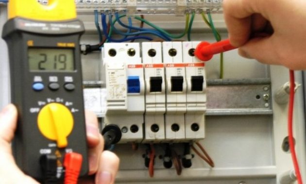
For identification, installers use two methods: the first is to check with an indicator screwdriver, and the second is to use a tester or multimeter. The phase is usually determined with a screwdriver, and neutral and zero with measuring instruments.
How to use the indicator?
Even devices as simple as indicator screwdrivers are different. Some of them are equipped with a small button, others are triggered automatically when a metal rod and a conductor or contact are connected.
But without exception, all models have a built-in LED that lights up under voltage.
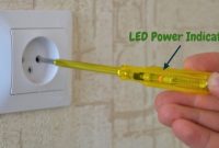
A screwdriver is a handy tool for identifying a phase conductor. To find out if the core is working, you need to gently touch the bare wire with a metal screwdriver shaft.
If the LED is on, the core is energized. No signal indicates that it is ground or zero.

The check procedure is performed with one hand, therefore, the other is free. It is better to use it as well – for example, to fix the wires. But it is strictly forbidden with the second hand to touch the bare parts of conductors or metal objects that are nearby (pipes, fittings).
Tester application rules
A tester or multimeter is always included with an electrician. He has to work with the connection of cores in electrical installations indoors and when assembling the electrical panel . If the wiring was installed a long time ago, the color marking of the wires can be neglected.
Even if the colors of the insulation seem to be consistent, it is not a fact that they are connected according to all the rules.

Before measurements, you should study the instructions that accompany all measuring devices.
The procedure is approximately as follows:
- set a value that is obviously higher than the expected voltage, for example, 260 V;
- connect the probes to the necessary sockets;
- touch the probes to two conductors – presumably the phase and neutral;
- repeat the procedure with another pair of conductors.
The combination of phase-zero conductors should give a result close to 220 V. It will always be higher than the phase-ground pair.
On sale there are both digital, modern devices, and outdated ones, with arrows and value scales. Digital is more convenient to use. Before installing electrical devices yourself, we recommend that you learn to use either an indicator screwdriver or a multimeter – you should not rely only on the color of the cores.
The ability to use a multimeter is useful for a home craftsman and for checking the voltage at the outlet. Detailed instructions on using the tester are given in this article .

