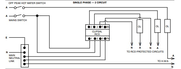
Hvordan koble til en RCD – Byggingen av et moderne internt elektrisk nett er en ansvarlig oppgave som involverer beregninger, ledningsvalg, og elektrisk installasjonsarbeid. One of the most important tasks in this case is to ensure the protection of residents and property. This article have example RCD wiring diagram for Hager CRD wiring diagram and Clipsall RCD wiring diagram
Do you agree with me?
All risks are minimized to a minimum if the protective devices are correctly chosen and the association diagram of the RCD and automatic devices is carefully considered. But how do you go about doing that?
What do you think about when making your decision? In our materials, we will respond to these and many other queries.
You will also learn how the RCD works and how to attach it to other devices. This content compiles expert recommendations and installation complexities. I tillegg, the article includes videos that show how the RCD connects in practice and explain the most common errors when connecting.
RCD’s purpose and operating principles

RCDs, unlike an automated system that protects the network from overloads and short circuits, are programmed to detect the existence of leakage current and disconnect the network or a separate electrical line immediately.
Due to the practical differences between these two security products, both must be included in the assembly diagram.
The RCD works on a basic principle: it compares the values of incoming and outgoing currents and triggers when there is a mismatch.
A diagram depicting the device’s function in the event of a phase breakdown. The voltage relay (PH) is turned on first, followed by the contactor (K)+.
A transformer with a core and windings with uniform magnetic flux guided in different directions is housed within the automatic device’s shell.
When a leakage current occurs, the output magnetic flux decreases, causing the electric relay to trip and the power supply to be turned on. If an individual comes into contact with a grounded system or an electrical circuit, this may happen. It takes between 0.2 og 0.4 seconds on average. We discussed the RCD’s device and operation theory in this article.
Tools for direct or alternating current networks come in a variety of shapes and sizes. The leakage current is a critical technical feature that must be present in the labeling.
Devices with a nominal value of 30 mA are chosen to secure the occupants of the building. They install a 10 mA RCD where there is a higher risk, such as bathrooms with high humidity or children’s playrooms.
Large current leaks can trigger a fire, so a higher rating, som for eksempel 100 mA or 300 mA, is intended to avoid it. These devices are commonly used as an introductory RCD in businesses and large facilities.+
RCD Wiring Diagram
The RCD (on the left) cannot be confused with a difavtomat (on the right), which combines the functions of a circuit breaker and an overload and leakage protection device. right now
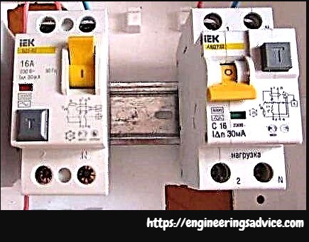
AEDT is more lightweight than a slew of safety devices and takes up less room in the control cabinet, but it makes it more difficult to determine what caused the shutdown when it is activated.
The installation scheme is chosen based on the function and the network form (one-phase or three-phase). RCDs are mounted at the power line’s input if the whole house or apartment needs to be protected from current leaks.+
Single-Phase Protection Wiring Diagram
Powerful domestic equipment manufacturers mention that a set of protective devices must be put into place. Accompanying information often indicates which equipment must also be installed in the network for washing machinery, electric stoves, dishwashers or boilers.
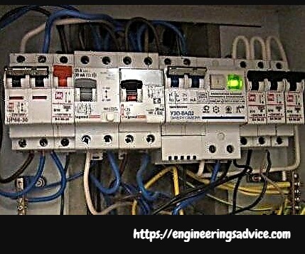
Several devices – on individual circuits or groups, men, are increasingly used. I dette tilfellet, the device is mounted in the shield together with the machine(s) and is connected to a specific line
We may assume that there are an infinite number of RCD link schemes when we consider the number of different circuits, serving sockets, switches, and equipment that loads the network as much as possible. You can even install a socket with an integrated RCD under domestic conditions.
Neste, we take into account the main popular connection options.
#1 – the 1-phase general RCD.

The RCD is located at the entrance to the apartment’s power line (house). It is installed entre a common 2-pole circuit breaker and circuit breakers to maintain different power lines – lighting, stikkontakter, household appliance branches, etc.
The safety system will automatically cut off all lines if a leakage current occurs on any of the outgoing circuits. This, selvfølgelig, is a disadvantage, as it will be impossible to pinpoint the exact location of the problem.+
Assume a current leak has occurred as a result of the phase wire making contact with a metal device linked to the network. The RCD trips, the voltage in the device drops, and determining the cause of the shutdown would be difficult.
On the plus side, one unit is less expensive and takes up less room in the electrical panel.
#2 RCD 1-phase network with a counter.

The existence of an electricity meter, which must be mounted, is a distinguishing characteristic of the circuit.
The devices are still protected against current leakage, but on the incoming side, a meter is mounted.
Switch off the general automated system, not the RCD, if you need to turn off the electricity to an apartment or building, even if they are both installed nearby and service the same network.
This arrangement has the same benefits as the previous one: it saves room on the electrical panel and money. The difficulty in detecting a leakage current is a drawback.
#3: RCDs for a 1-phase Wiring Doagram.

One of the more complex variants of the previous edition is this scheme.
The defense against leakage currents is doubled thanks to the inclusion of additional devices on each working circuit. This is a fantastic choice in terms of defense.
Assume an emergency current leakage occurred, and the lighting circuit’s attached RCD failed for whatever reason. The general system then reacts by disconnecting all of the wires.
It is important to observe selectivity, det er, when installing, take into account both the response time and the current characteristics of the devices, so that both (private and general) devices do not operate immediately.
The circuit’s positive side is that one circuit will shut off in an emergency. It’s incredibly uncommon for the whole network to go down.+
If an RCD mounted on a
- specific line is faulty,
- out of order, eller
- does not fit the load, this may happen.
We suggest that you become acquainted with the methods for testing the RCD for operability to avoid such situations.
Cons: Overcrowding of the electrical panel with a slew of identical instruments, as well as extra costs.
#4 1-phase Wiring Diagram With a Group of RCDs.
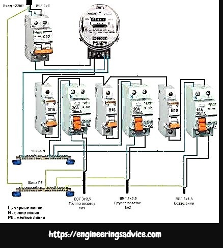
Practice has shown that the circuit can work without the use of a common RCD.+
Selvfølgelig, there is no one-size-fits-all security against failure, but this can be easily remedied by purchasing a more costly product from a reputable manufacturer.
The scheme resembles a general-protection alternative, but without the need to install an RCD for each individual group. It has a significant advantage in that it is easier to pinpoint the source of the leak.
In terms of cost, the wiring of multiple devices is inefficient; one typical device will be much less expensive.+
If your apartment’s electrical system isn’t grounded, we suggest familiarizing yourself with the RCD link diagrams without grounding.
Options For 3-phase Protection
There might be a different way to arrange power supply in homes, industrial buildings, and other structures.
Som et resultat, though connecting a 3-phase network to an apartment is unusual, it is not uncommon to do so to equip a private residence. Other security system linking schemes would be used in this situation.+
#1 3-phase RCD and group RCDs wiring Connection
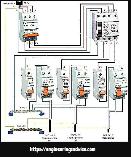
A 2-pole system is insufficient for a 380 I nettverket; a 4-pole analog is needed, with one zero core and three phase conductors connected.
The equipment of each power line with a separate RCD unit complicates the circuit. While duplicate security is optional, it is recommended for additional protection against leakage currents.
It’s crucial to know what kind of wires you’re using. A regular VVG cable is ideal for a 1-phase network, but a more resistant to ignition VVGng is recommended for a 3-phase network. In our previous post, we discussed how to choose the right wire.+
#2 RCD For a 3-Phase Wiring Connection With a Counter.
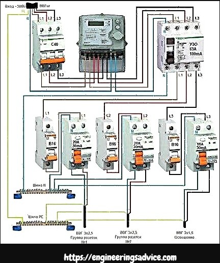
This solution is identical to the previous one, with the exception that an energy meter has been attached to the circuit. Person line support systems provide group RCDs as well.
This is the most voluminous circuit in the sense that it necessitates the construction of a huge electrical panel with numerous wires and connected electrical appliances.
There is a nuance that can be applied to all of the schemes presented. It makes sense to install double security with a typical RCD if there are several lighting and outlet circuits in the apartment or home, as well as several strong household appliances that require the arrangement of separate power lines.+
In the opposite case, either a single apparatus or one for each circuit is necessary.
RCD installation instructions
You must first select a location for the unit to be installed. Shield or cabinet are the two choices. The first looks like a metal box with no lid, fixed at a comfortable maintenance height.
A lockable door is included in the cabinet. Some cabinets have openings that allow you to take meter readings and switch off the unit without having to open the door.
Protective sensors are mounted horizontally on mounting DIN rails. The modular design of automatic machines, such as difavtomatov and UZO, enables several parts to be placed on a single track.
At the input and output, a neutral wire is often wired to the left terminals, and the phase wire to the right. One possibility is:
- input terminal N (upper left) – from the introductory machine;
- output N (lower left) – to a separate zero bus;
- input terminal L (upper right) – from the introductory machine;
- output L (lower right) – to group machines.
Circuit breakers may be mounted on the switchboard until the safety system is installed. You may need to rearrange the equipment in a specific order to coordinate the wires and devices.
We show how to mount an input RCD in an electrical cabinet that already has a meter, an input circuit breaker, and multiple circuit breakers for individual circuits such as lighting, stikkontakter, og så videre.
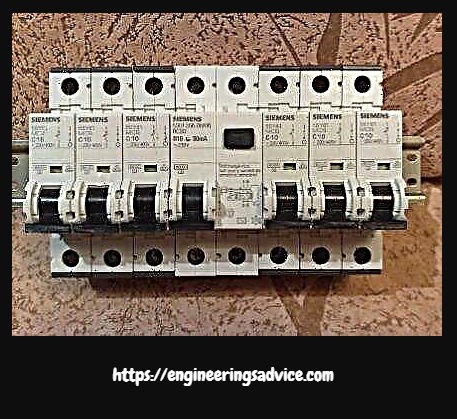
The shield’s dimensions are determined by the number of devices inside. When installing new machines and RCDs, it is preferable to select a product with a wide margin.
A home electricity meter is pre-installed on a DIN rail in one row (from left to right), followed by one input switch and five community machines.
The best installation location, as determined by system operation, is between the input machine and other devices serving individual lines (outlet, etc.)
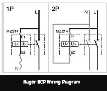
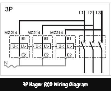
Hager RCD Wiring Diagram
The over and undervoltage auxiliary is mounted on the left side of the associated hager MCB / RCCB / RCBO

CLIPSAL RCD Wiring Diagram
1p Clipsal RCD with 1 Circuit

1p Clipsal RCD with 2 Circuit
1p Clipsal RCD with 3 Circuit
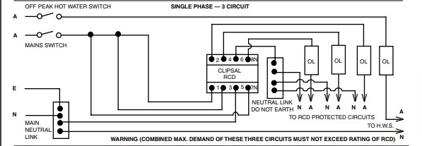
2p Clipsal RCD

Overview RCD Wiring Diagram
- Place the gadget on the right-hand DIN rail of the unit – simply connect it and force it until it clicks;
- We extend the cut and stripped wires from the unit and the zero bus, then insert them into the upper terminals as shown in the diagram and tighten the screws.
- Attach the wires into the lower terminals and tighten the screws in the same manner;
- Switch on the general computer first, then the RCD, then push the “Test” button; the system should turn off when pushed.
- Switch on the general computer first, then the RCD, then push the “Test” button; the system should turn off when pushed.
The leakage current is often staged to ensure that the connection is right. Bring two working wires – “step” og “ground” – to the lamp’s base at the same time. When a leak occurs, the system can trip immediately.

